|
|
|
Y27 Series Connector |
|
The connector, which operate easily and connect reliably, is available for blind or other mating. They also have the characteristics of anti-vibration, salt spray resistance, EMI shielding. And there are the varieties of dust resistance, rainproof and hermetic, etc.
|
|
|
|
|
| Brief introductionY27 Series Y27 Series | top ↑ |
Y27 Series Y27 SeriesThe connector, which operate easily and connect reliably, is available for blind or other mating. They also have the characteristics of anti-vibration, salt spray resistance, EMI shielding. And there are the varieties of dust resistance, rainproof and hermetic, etc.
The series of connectors have diversity of sizes, and consists of Y27F, Y27G with rear accessories fitting the ship conditions. |
Y27 Series Y27 Series |
| specificationY27 Series Y27 Series | top ↑ |
Y27 Series Y27 Series1. Rated Current of contact (A) | Contact Size (mm) | 0.8 | 1.0 | 1.5 | 2.5 | 3.5 | 5.0 | 7.0 | 9.0 | 10.0 | Rated Current
of Contact (A) | Y27 | 3 | - | - | - | - | - | - | - | - | Y27A | - | 5 | - | - | - | - | - | - | - | Y27B | - | 5 | 10 | 25 | 50 | 75 | 100 | 150 | 200 | Y27C | - | 5 | 10 | 25 | 50 | 75 | 100 | 150 | 200 | Y27F | - | 7.5 | - | - | - | - | - | - | - | Y27G | - | 7.5 | 13 | 25 | 50 | 75 | 100 | 150 | 200 | Symbol |  |  |  |  |  |  |  |  |  |
2. Working voltage (V): | Series Numbers | DC | AC | Y27 | 150 | 100 | Y27A, Y27B | 350 | 250 | Y27C, Y27F, Y27G | 700 | 500 |
3. Contact resistance (milliohm ): | Contact Size | 0.8 | 1 | 1.5 | 2.5 | 3.5 | 5 | 7 | 9 | 10 | Material | Copper | Iron | Copper | Iron | Copper | Iron | Copper | Iron | Copper | Copper | Copper | Copper | Copper | Before Aging Test | 7 | 25 | 5 | 12 | 3 | 10 | 1.5 | 5 | 1 | 0.7 | 0.5 | 0.4 | 0.4 | After Aging Test | 10 | 32 | 10 | 20 | 5 | 15 | 3 | 10 | 1.5 | 1 | 0.8 | 0.7 | 0.6 |
4. Dielectric with standing voltage (V): | Conditions | Test Voltage(50Hz, RMS) | Series Number | Y27 | Y27A | Y27B | Y27C | Y27F | Y27G | In Standard Conditions | 750 | 1300 | 1500 | 2500 | 2300 | 2300 | In Low Atmospheric Pressure
(less than 1.33Pa ) | 100 | 200 | 200 | 300 | 300 | 300 |
5. Insulation resistance (megohms): | Series Number | Y27 | Y27A | Y27B | Y27C | Y27F | Y27G | Standard Conditions | 1000 | 4000 | 5000 | 5000 | 5000 | 5000 | At High
Temperature | Ordinary | 500 | 1000 | 1000 | 1000 | 1000 | 1000 | Hermetic | 200 | 200 | 200 | 200 | | | In Wet and Hot Conditions | 50 | 100 | 100 | 100 | 100 | 100 | In Rain | 20 | 20 | 20 | 20 | - | - | Water Immersion | - | - | - | - | 20 | 20 |
| 6. Conductivity of shell: | Shell-to-shell conductivity | a. 10 milliohm (aluminum shell) | b. 50 milliohm (material of the shell of either plug or socket is stainless-steel or ferroalloy) |
| 7. Air-tightness of socket: | Rubber seal | leakage is less than 1 x 10⁻³ Pa.L/s | Sintered seal | leakage is less than 1 x 10⁻⁷ Pa.L/s |
Y27 Series Y27 Series |
| Product Outline DimensionsY27 Series Y27 Series | top ↑ |
Y27 Series Y27 Series1. Outline dimension of push/pull release plug | 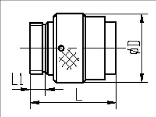 | Shell size | D | Y27?Y27A
Y27B?Y27C | Y27F?Y27G | L | L1 | L | L1 | 08 | 19.5 | 31 | 5 | 32 | 6 | 10 | 21.5 | 31 | 5 | 32 | 6 | 12 | 23.5 | 31 | 5 | 32 | 6 | 14 | 26 | 31 | 5 | 32 | 6 | 16 | 28 | 31 | 5 | 32 | 6 | 18 | 30 | 31 | 5 | 32 | 6 | 20 | 33.5 | 31 | 5 | 32 | 6 | 22 | 36.5 | 31 | 5 | 32 | 6 | 24 | 39.5 | 32 | 6 | 34 | 7 | 26 | 43 | 32 | 6 | 34 | 7 | 28 | 46 | 32 | 6 | 34 | 7 | 30 | 50 | 37 | 6 | 38 | 7 | 32 | 53 | - | - | 38 | 7 |
2. Outline dimension of lanyard release plug | 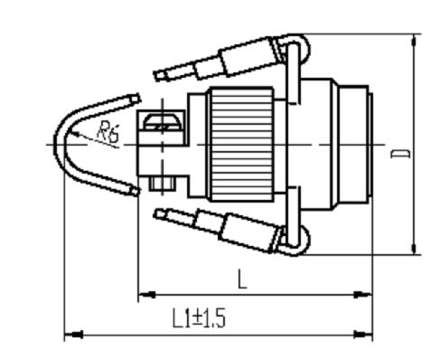 | Sub-serial number | Shell size | Number of contact | D | L | L1 | Y27A | 16 | 19 | 46.6 | 47.5 | 120 | Y27B | 22 | 14 | 58.6 | 65.5 | 132 | Note: a. Unlocking distance is no more than 2.5 centimeter when the series Y27A-1619 is under the load of axial unlocking force whose value is 49.1N b. Unlocking distance is no more than 2.5 centimeter when the series Y27B-2214 is under the load of axial unlocking force whose value is 80N. |
| 3. Cable mounting receptacle (series Y27?Y27A?Y27B and Y27C): dimension of outline .(form of mount: L) | 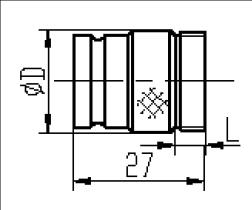 | Shell size | 08 | 10 | 12 | 14 | 16 | 18 | 20 | 22 | 24 | 26 | 28 | 30 | D | 14 | 16 | 18 | 20 | 22 | 24 | 27 | 30 | 33 | 36 | 39 | 42 | L | 5 | 5 | 5 | 5 | 5 | 5 | 5 | 5 | 6 | 6 | 6 | 6 |
4. Receptacle: rubber-sealing, square flange mounting, dimension of outline and mount | Series Y27?Y27A | 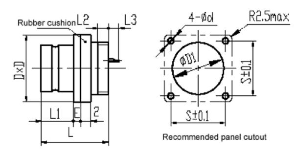 | Shell size | D | S | D1 | d | E | L | L1 | L2 | L3max | Form of mount | 08 | 21 | 15 | 14.5 | 3.6 | 1.5 | 27 | 16 | 4.5 | 0 | B | 10 | 22 | 16 | 16.5 | 3.6 | 1.5 | 27 | 16 | 4.5 | 0 | B | 10 | 24 | 18 | 16.5 | 3.6 | 1.5 | 27 | 16 | 4.5 | 0 | B1 | 12 | 24 | 18 | 18.5 | 3.6 | 1.5 | 27 | 16 | 4.5 | 1 | B | 14 | 26 | 20 | 20.5 | 3.6 | 1.5 | 27 | 16 | 4.5 | 1 | B | 14 | 27 | 21 | 20.5 | 3.6 | 1.5 | 27 | 16 | 4.5 | 1 | B1 | 16 | 27 | 21 | 22.5 | 3.6 | 1.5 | 27 | 16 | 4.5 | 1 | B | 16 | 29 | 23 | 22.5 | 3.6 | 1.5 | 27 | 16 | 4.5 | 1 | B1 | 18 | 30 | 23 | 24.5 | 3.6 | 1.5 | 27 | 16 | 4.5 | 2 | B | 20 | 32 | 25 | 27.5 | 3.6 | 1.5 | 27 | 16 | 4.5 | 3 | B | 22 | 35 | 27 | 30.5 | 3.6 | 1.5 | 27 | 16 | 4.5 | 3 | B | 24 | 37 | 29 | 33.5 | 3.6 | 2.2 | 27 | 16 | 4.5 | 0 | B | 24 | 41 | 32 | 33.5 | 3.6 | 2.2 | 27 | 16 | 4.5 | 0 | B1 | 26 | 40 | 31 | 36.5 | 3.6 | 2.2 | 27 | 16 | 4.5 | 0 | B | 26 | 44 | 35 | 36.5 | 3.6 | 2.2 | 27 | 16 | 4.5 | 0 | B1 |
| Series of Y27B (form of mount: B) | Shell size | D | S | D1 | d | E | L | L1 | L2 | L3max | 12 | 24 | 18 | 18.5 | 3.6 | 1.5 | 27 | 16 | 4.5 | 2 | 16 | 27 | 21 | 22.5 | 3.6 | 1.5 | 27 | 16 | 4.5 | 2 | 20 | 32 | 26 | 27.5 | 3.6 | 1.5 | 27 | 16 | 4.5 | 7 | 22 | 35 | 27 | 30.5 | 3.6 | 1.5 | 27 | 16 | 4.5 | 2 | 24 | 42 | 33 | 33.5 | 5.5 | 2.2 | 27 | 16 | 4.5 | 5 | 26 | 42 | 32 | 36.5 | 3.6 | 2.2 | 27 | 16 | 4.5 | 2 |
| Series of Y27C (form of mount: B) | Shell size | D | S | D1 | d | E | L | L1 | L2 | L3max | 16 | 27 | 21 | 22.5 | 3.6 | 1.5 | 27 | 16 | 4.5 | 2 | 20 | 32 | 25 | 27.5 | 3.6 | 1.5 | 27 | 16 | 4.5 | 2 | 26 | 43 | 34 | 36.5 | 5.5 | 2.2 | 27 | 16 | 4.5 | 5 | 30 | 50 | 40 | 42.5 | 5.5 | 2.2 | 27 | 16 | 4.5 | 7 |
Series of Y27F,Y27G (form of mount: B) | Shell size | D | S | D1 | d | E | L | L1 | L2 | L3max
(F) | L3max
(G) | 08 | 21 | 15 | 14.5 | 3.6 | 1.5 | 29 | 17.5 | 5.5 | 1.2 | 1.2 | 10 | 22 | 16 | 16.5 | 3.6 | 1.5 | 29 | 17.5 | 5.5 | 1.2 | 1.2 | 12 | 24 | 18 | 18.5 | 3.6 | 1.5 | 29 | 17.5 | 5.5 | 1.2 | 2.2 | 14 | 26 | 20 | 20.5 | 3.6 | 1.5 | 29 | 17.5 | 5.5 | 1.2 | 1.2 | 16 | 27 | 21 | 22.5 | 3.6 | 1.5 | 29 | 17.5 | 5.5 | 1.2 | 1.2 | 18 | 30 | 23 | 24.5 | 3.6 | 2 | 29 | 17.5 | 5.5 | 1.2 | 1.2 | 20 | 33 | 26 | 27.5 | 3.6 | 2 | 29 | 17.5 | 5.5 | 1.2 | 1.2 | 22 | 36 | 28 | 30.5 | 3.6 | 2 | 29 | 17.5 | 5.5 | 1.2 | 1.2 | 24 | 39 | 31 | 33.5 | 3.6 | 2.5 | 29 | 17.5 | 5.5 | 1.2 | 1.2 | 26 | 42 | 33 | 36.5 | 3.6 | 2.5 | 29 | 17.5 | 5.5 | 1.2 | 1.2 | 28 | 45 | 36 | 39.5 | 3.6 | 2.5 | 29 | 17.5 | 5.5 | 1.2 | 1.2 | 30 | 49 | 39 | 42.5 | 5.5 | 2.5 | 29 | 17.5 | 5.5 | 1.2 | 1.2 | 32 | 52 | 42 | 45.5 | 5.5 | 2.5 | 29 | 17.5 | 5.5 | 1.2 | 6 |
5. Receptacle (series Y27): sinter-sealing, square flange mounting, dimension of outline and mount (form of mount: B) | 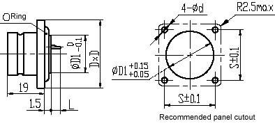 | Sub-serial number | Shell size | Number of contact | Type of contact | D | S | D1 | d | Lmax | Y27 | 14 | 24 | J1 | 26 | 20 | 15.5 | 3.6 | 2 | Y27 | 14 | 30 | J1 | 26 | 20 | 15.5 | 3.6 | 2 | Y27 | 22 | 61 | J1 | 35 | 27 | 25.5 | 3.6 | 4 | Note: Type of contact—pin. |
6. Receptacle (series Y27 and Y27A): sinter-sealing, square flange mounting, dimension of outline and mount (form of mount: B1) | 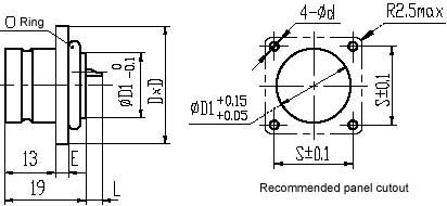 | Shell size | D | S | D1 | d | E | Lmax | 14 | 30 | 23.5 | 16.5 | 3.6 | 2 | 2 | 16 | 31.5 | 25 | 18.5 | 3.6 | 2 | 2 | 22 | 37.5 | 31 | 26.5 | 3.6 | 2.5 | 2 | Note: Type of contact—pin. |
7. Receptacle: rubber-sealing, nut mounting, dimension of outline and mount (form of mount: B2) | 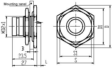 | Sub-series number | Shell size | D | D1 | S | S1 | D2 | Bmin | Bmax | Lmax | Remark | Y27A | 26 | 55.5 | 48.5 | 48 | 42 | 36 | 2 | 4.5 | 0 | Developing | Y27B | 26 | 55.5 | 48.5 | 48 | 42 | 36 | 2 | 4.5 | 2 | Developing | Y27C | 26 | 55.5 | 48.5 | 48 | 42 | 36 | 2 | 4.5 | 5 | - |
8. Receptacle (series Y27): sinter-sealing, solder, dimension of outline and mount (form of mount: B3) | 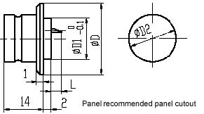 | Shell size | D | D1 | D2 | Lmax | Remark | 08 | 16 | 10 | 10.5 | 1 | Developing | 10 | 18 | 12 | 12.5 | 1 | Developing | 12 | 20 | 14 | 14.5 | 2 | Developing | 14 | 22.5 | 17 | 17.5 | 2 | - | 16 | 24.5 | 19 | 19.5 | 2 | Developing | 18 | 26.5 | 21 | 21.5 | 3 | Developing | 20 | 29.5 | 24 | 24.5 | 4 | Developing | 22 | 32.5 | 27 | 27.5 | 4 | Developing | Note: type of contact—pin. |
9. Receptacle: rubber-sealing, switch, dimension of outline and mount (form of mount: B4) | 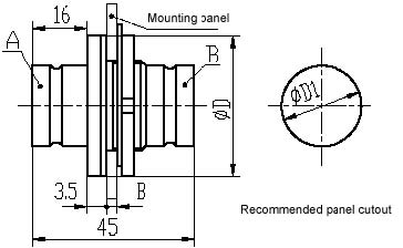 | Sub serial number | Shell size | Type of contact | D | D1 | Bmin | Bmax | Y27A?Y27B | 22 | Not remark | 40 | 30.5 | 1.5 | 5 | Y27A?Y27B | 24 | Not remark | 43 | 33.5 | 1.5 | 5 | Y27A?Y27B?Y27C | 26 | Not remark | 46 | 36.5 | 1.5 | 5 | Note: types of contact of the “A” end and “B” end separately are pin type and socket type. |
10. Receptacle: sinter-sealing, switch, dimension of outline and mount (form of mount: B4) | 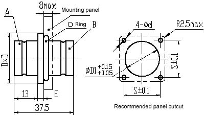 | Sub serial number | Shell size | Number of contact | Type of contact | D | S | D1 | d | Lmax | Y27A | 16 | 19 | J | 31.5 | 25 | 20.5 | 3.6 | 2 | Y27A | 22 | 37 | J | 37.5 | 31 | 28.5 | 3.6 | 2.5 | Y27 | 22 | 55 | J | 37.5 | 31 | 28.5 | 3.6 | 2.5 | Y27B | 22 | 14 | J | 37.5 | 31 | 28.5 | 3.6 | 2.5 | Note: identifying numbers of angle between main keyway and auxiliary keyway from the “A” end and “B” end are separately marked with ? and ?. Sign of the plug mated with B end should be finally added the character “W”. |
11. Outline dimension of type ? rear accessories | 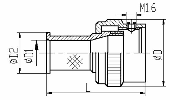 | Matched shell size | D | D1 | D2 | L | 08 | 19 | 5.5 | 9.5 | 36 | 10 | 21 | 7.5 | 11.5 | 36 | 12 | 23 | 9.5 | 13.5 | 36 | 14 | 25 | 11.5 | 15.5 | 36 | 16 | 27 | 13.5 | 17.5 | 37 | 20 | 33 | 18.5 | 22.5 | 38 | 22 | 36 | 21.5 | 25.5 | 39 | 24 | 39 | 23.5 | 27.5 | 39 | 26 | 42 | 26.5 | 30.5 | 42 |
12. Outline dimension of type ? rear accessories | 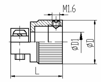 | Matched shell size | D | D1 | L | 08 | 17 | 6 | 19 | 10 | 19 | 8 | 19 | 12 | 20 | 8 | 19 | 14 | 22 | 10 | 20 | 16 | 24 | 12 | 22 | 18 | 26 | 12 | 22 | 20 | 29 | 16 | 24 | 22 | 32 | 18 | 25 | 24 | 37 | 24 | 26 | 26 | 39 | 26 | 29 | 28 | 41 | 26 | 29 | 30 | 44 | 30 | 35 | 32 | 47 | 36 | 38 |
13. Outline dimension of type ? rear accessories | 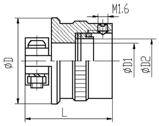 | Matched shell size | D | D1 | D2 | L common | L lengthening | 16 | 35 | 22 | 15.8 | 32 | - | 20 | 37 | 24 | 20.8 | 32 | - | 26 | 46 | 28 | 29 | 40 | 53 | 30 | 54 | 36 | 35 | 56 | 85 |
14. Outline dimension of type ? rear accessories | 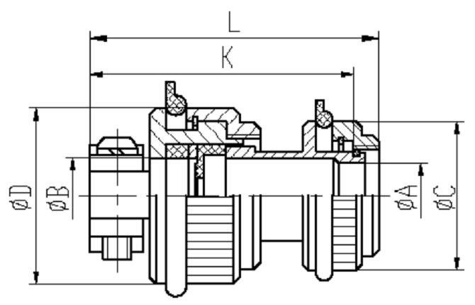 | Type of rear accessories | A | B | C | D | K | L | Tmin | Tmax | Y27-10VA | 9.6 | 11 | 23 | 27 | 54 | 59 | 6.0 | 11.0 | Y27-10VD | 9.6 | 13 | 23 | 29 | 54 | 59 | 6.0 | 13.0 | Y27-12VA | 11.6 | 11 | 25 | 27 | 46 | 51 | 6.0 | 11.0 | Y27-12VB | 11.6 | 13 | 25 | 29 | 54 | 59 | 8.0 | 13.0 | Y27-12VC | 11.6 | 15 | 25 | 31 | 54 | 59 | 10.0 | 15.0 | Y27-12VD | 11.6 | 18 | 28 | 34 | 54 | 59 | 12.0 | 18.0 | Y27-14VA | 13.6 | 11 | 26 | 27 | 47 | 52 | 6.0 | 11.0 | Y27-14VB | 13.6 | 13 | 26 | 29 | 47 | 52 | 8.0 | 13.0 | Y27-14VD | 13.6 | 15 | 26 | 31 | 57 | 62 | 10.0 | 15.0 | Y27-16V | 15.6 | 11 | 28 | 27 | 47 | 52 | 6.0 | 11.0 | Y27-16VA | 15.6 | 15 | 28 | 31 | 49 | 54 | 10.0 | 15.0 | Y27-16VB | 15.6 | 18 | 28 | 34 | 60 | 65 | 12.0 | 18.0 | Y27-18VA | 17.6 | 15 | 31 | 31 | 49 | 54 | 10.0 | 15.0 | Y27-18VB | 17.6 | 18 | 31 | 34 | 60 | 65 | 10.0 | 18.0 | Y27-18VD | 17.6 | 21 | 31 | 37 | 65 | 70 | 12.0 | 21.0 | Y27-18VF | 17.6 | 24 | 34 | 40 | 65 | 70 | 14.0 | 24.0 | Y27-20VA | 20.6 | 18 | 34 | 34 | 51 | 56 | 12.0 | 18.0 | Y27-20VB | 20.6 | 21 | 34 | 37 | 68 | 73 | 14.0 | 21.0 | Y27-20VC | 20.6 | 24 | 34 | 40 | 68 | 73 | 16.0 | 24.0 | Y27-20VD | 20.6 | 27 | 37 | 43 | 68 | 73 | 18.0 | 27.0 | Y27-22VA | 23.6 | 21 | 37 | 37 | 57 | 62 | 14.0 | 21.0 | Y27-22VB | 23.6 | ,24 | 37 | 40 | 71 | 76 | 16.0 | 24.0 | Y27-22VC | 23.6 | 27 | 37 | 43 | 71 | 76 | 18.0 | 27.0 | Y27-22VD | 23.6 | 33 | 43 | 51 | 76 | 81 | 22.0 | 33.0 | Y27-24VA | 25.6 | 21 | 40 | 37 | 57 | 63 | 14.0 | 21.0 | Y27-24VB | 25.6 | 24 | 40 | 40 | 57 | 63 | 16.0 | 24.0 | Y27-24VC | 25.6 | 27 | 40 | 43 | 71 | 77 | 18.0 | 27.0 | Y27-24VD | 25.6 | 30 | 40 | 48 | 71 | 77 | 20.0 | 30.0 | Y27-24VE | 25.6 | 36 | 46 | 54 | 76 | 82 | 24.0 | 36.0 | Y27-26VA | 28.6 | 24 | 42 | 40 | 59 | 65 | 16.0 | 24.0 | Y27-26VB | 28.6 | 27 | 42 | 43 | 59 | 65 | 18.0 | 27.0 | Y27-26VC | 28.6 | 30 | 42 | 48 | 74 | 80 | 20.0 | 30.0 | Y27-28VA | 31.6 | 27 | 46 | 43 | 59 | 65 | 18.0 | 27.0 | Y27-28VB | 31.6 | 30 | 46 | 48 | 59 | 65 | 20.0 | 30.0 | Y27-28VC | 31.6 | 33 | 46 | 51 | 81 | 87 | 22.0 | 33.0 | Y27-28VD | 31.6 | 39 | 49 | 57 | 81 | 87 | 28.0 | 39.0 | Y27-28VE | 31.6 | 46 | 56 | 65 | 81 | 87 | 28.0 | 46.0 | Y27-32VA | 37.6 | 46 | 58 | 65 | 81 | 87 | 28.0 | 46.0 | Note: T—allowable external diameter of cable sheath met with sealing ring of rear accessories. |
15. Outline dimension of type ? rear accessories | 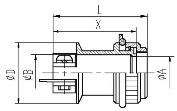 | Type of rear accessories | A | B | D | X | L | Y27-10?A | 12 | 12 | 27 | 30 | 35 | Y27-12?A | 12 | 12 | 27 | 30 | 35 | Y27-12?B | 14 | 16 | 31 | 40 | 45 | Y27-14?A | 14 | 14 | 29 | 35 | 40 | Y27-16?A | 16 | 16 | 31 | 35 | 40 | Y27-18?A | 19 | 19 | 34 | 35 | 40 | Y27-18?B | 20 | 22 | 37 | 50 | 55 | Y27-20?A | 22 | 22 | 37 | 45 | 50 | Y27-20?B | 23 | 25 | 40 | 55 | 60 | Y27-22?A | 25 | 25 | 40 | 45 | 50 | Y27-22?B | 26 | 28 | 43 | 55 | 60 | Y27-24?A | 25 | 25 | 40 | 45 | 51 | Y27-24?B | 28 | 31 | 48 | 60 | 66 | Y27-26?A | 28 | 28 | 43 | 50 | 56 | Y27-28?A | 31 | 31 | 48 | 55 | 61 | Y27-28?B | 34 | 40 | 57 | 65 | 71 | Y27-32?A | 41 | 46 | 64 | 65 | 71 |
16. Outline dimension of protective cap (plug) made of metal | 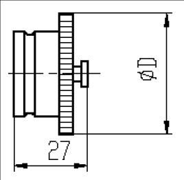 | Matched shell size | 08 | 10 | 12 | 14 | 16 | 18 | 20 | 22 | 24 | 26 | 30 | D | 20 | 22 | 24 | 26.5 | 28.5 | 30.5 | 33.5 | 36.5 | 39 | 45 | 52 |
17. Outline dimension of protective cap (receptacle) made of metal | 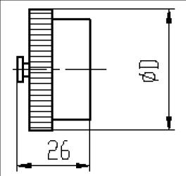 | Matched shell size | 08 | 10 | 12 | 14 | 16 | 18 | 20 | 22 | 24 | 26 | 30 | D | 20.5 | 22.5 | 24.5 | 27 | 29 | 31 | 34 | 37 | 39.5 | 43 | 48 |
|
| Contact ArrangementsY27 Series Y27 Series | top ↑ |
Y27 Series Y27 Series1.Series Y27 contact arrangement |  | 2.Series Y27A contact arrangement | 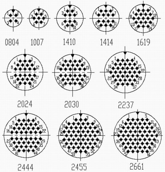 | 3.Series Y27B contact arrangement | 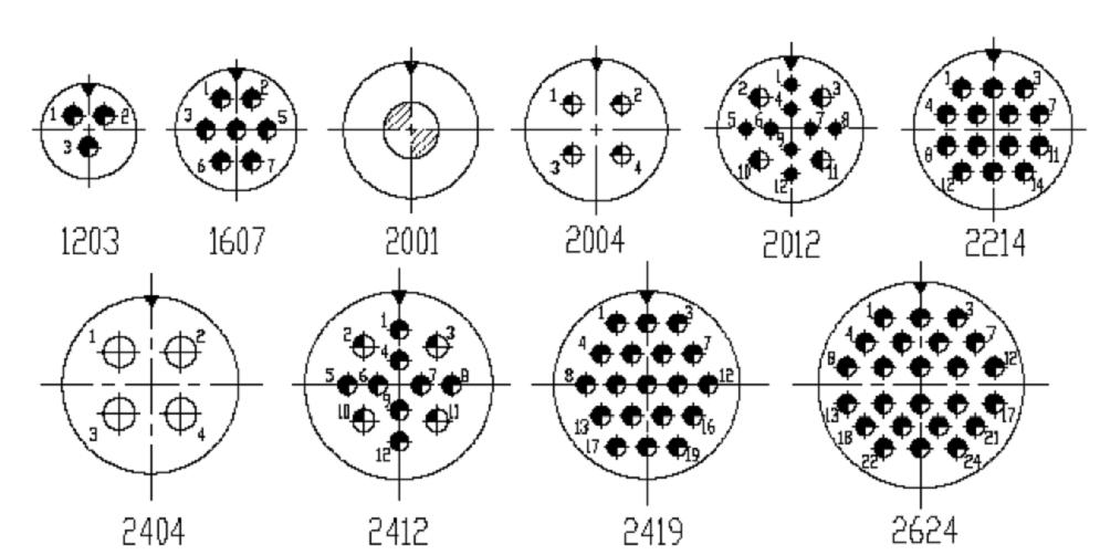 | 4.Series Y27C contact arrangement |  | 5. Series Y27F contact arrangement | 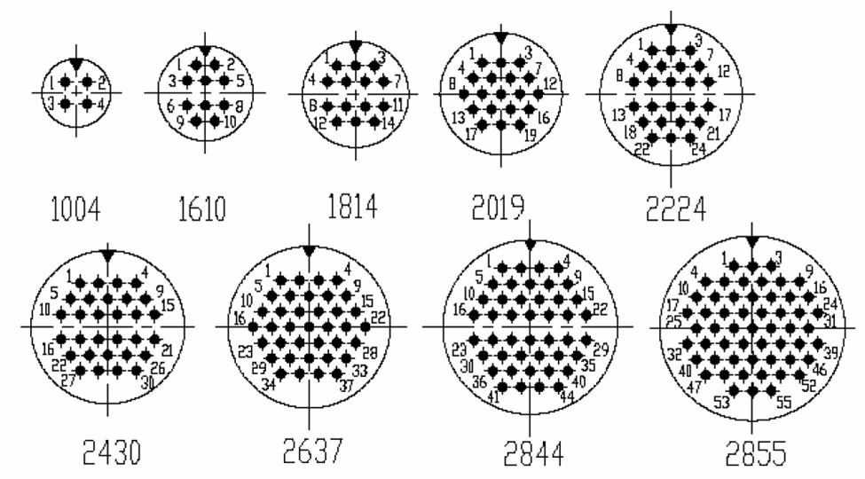 | 6. Series Y27G contact arrangement | 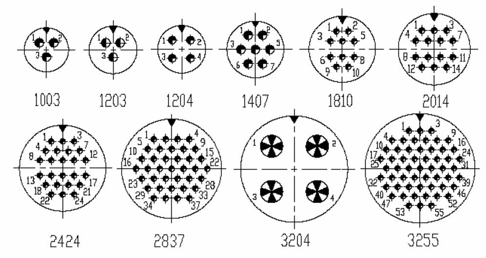 | Explanation: 1. --The position of main-key (keyway) 2. Cavity identifying numbers in the figure of contact arrangement shown here all represent cavity identifying numbers of the socket in the mating interface. 3. four digit are under the figure of contact arrangement, previous two digit of which represent shell size and subsequent two digit of which represent number of contact. 4. Size and sign of contact in the characteristic |
Y27 Series Y27 Series |
| For ExampleY27 Series Y27 Series | top ↑ |
Y27 Series Y27 SeriesType of products | Code name of performed specification | Y27 A B C | Q/Jc123-93 | Y27 A B C (Class "F") | Q/Jc176-99 | Y27A (Production line according to military standards) | Q/YJc196A-2000 | Y27F G | Q/Jc140-96 | 1. Mark of the plug interpretation | 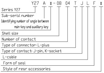 | Note: 1) identifying number of angle between main-key and auxiliary key: ?(allow to be omitted) ????? 2) Shell size and number of contact of all series seeing contact arrangement. 3) type of contact Series Y27: J1 (K1)—soldering end of contact (having shoulder, back to back, arrangement in two directions). Series Y27A: J (K)—soldering end of contact (uniformly flat, back to back, arrangement in two directions), J1 (K1) —soldering end of contact (having shoulder, back to back, arrangement in two directions), J3 (K3) —removable crimp contact. Series Y27B: J (K)—soldering end of contact (uniformly flat, arrangement in one direction). Series Y27C: J (K)—soldering end of contact (uniformly flat, arrangement in one direction). J1 (K1)—soldering end of contact (uniformly flat, back to back, arrangement in two directions). Series Y27F: J (K)—soldering end of contact (uniformly flat, arrangement in one direction). Series Y27G: J (K)—soldering end of contact (uniformly flat, arrangement in one direction). J1 (K1)—soldering end of contact (uniformly flat, back to back, arrangement in two directions). 4) Form of release: A(allow to be omitted)—push/pull F—lanyard release 6) Style of rear accessories: —without rear accessories ?--mated with?style of rear accessories, ?--mated with ? style of rear accessories, ?--mated with ? style of rear accessories, ?-- mated with ? style of rear accessories,?--mated with ? style of rear accessories. Series Y27 , Y27A, Y27B, Y27C only are mated with ?,?,? style of rear accessories and are not mated with ?, ? style of rear accessories. | 2. Mark of the receptacle interpretation | 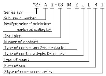 | Note: 1) identifying number of angle between main keyway and auxiliary keyway: ?(allow to be omitted) ????? 2) Shell size and number of contact of all series seeing contact arrangement. 3) type of contact Series Y27: J1 (K1)—soldering end of contact (having shoulder, back to back, arrangement in two directions). Series Y27A: J (K)—soldering end of contact (uniformly flat, back to back, arrangement in two directions), J1 (K1) —soldering end of contact (having shoulder, back to back, arrangement in two directions), J3 (K3) —removable crimp contact. Series Y27B: J (K)—soldering end of contact (uniformly flat, arrangement in one direction). Series Y27C: J (K)—soldering end of contact (uniformly flat, arrangement in one direction). J1 (K1)—soldering end of contact (uniformly flat, back to back, arrangement in two directions). Series Y27F: J (K)—soldering end of contact (uniformly flat, arrangement in one direction). Series Y27G: J (K)—soldering end of contact (uniformly flat, arrangement in one direction). J1 (K1)—soldering end of contact (uniformly flat, back to back, arrangement in two directions). 4) Type of mount: L—cable type mounting, B—square flange mounting, B1—square flange mounting, B2—nut mounting, B3—tin-solder mounting B4—switch type ( J(only for B4 type ): contacts in two ends of the receptacle are all pins. When omitting the symbol of J, contacts in the end of the receptacle are pins and contacts in the other end of receptacle are socket. 5) Form of seal: P (allow to be omitted)—non-sealing M-rubber-sealing H-glass-sintering seal 6) Style of rear accessories: —without rear accessories ?--mated with?style of rear accessories, ?--mated with style of rear accessories, ?--mated with ? style of rear accessories, ?-- mated with ? style of rear accessories,?--mated with ? style of rear accessories. Series Y27 , Y27A, Y27B, Y27C only are mated with ?,?,? style of rear accessories and are not mated with ?, ? style of rear accessories. | |
Y27 Series Y27 Series |
| Notice for Selecting and UsingY27 Series Y27 Series | top ↑ |
Y27 Series Y27 Series1. pay attention to distinction of the key position (I, II, III ) of the plug and the receptacle. 2. pay attention to difference in the dimension of B and B1 of square flange mounting receptacle 3. pay attention to difference in configuration and exit dimension of rear accessories( II, III, IV, V, VII) |
Y27 Series Y27 Series |
| Environmental ConditionY27 Series Y27 Series | top ↑ |
Y27 Series Y27 SeriesEnvironment temperature range | Y27, Y27A, Y27F series | -55- +100oC | Y27B, Y27C, Y27G series | -55- +80oC | Operating temperature range | Y27, Y27A, Y27F series | -55- +125oC | Y27B, Y27C, Y27G series | -55- +125oC | Atmospheric pressure | 101.3kPa- 1.33Pa | Relative humidity | up to (95+3, -3)% at 40+2, -2oC | Vibration | Sin | 196m/s2 from 10-2000Hz | Random | 39m2 /s4 Hz (0.4g2 /Hz) , 226m/s2 (RMS) | Shock | 980m/s2 | Constant acceleration | 980m/s2 | Salt spray resistance | series of Y27F, Y27G :96h; series of Y27, Y27A,B,C :48h | EMI shielding | a minimum of 45dB effectiveness over a range of 100MHz to 1GHz | Water Immersion | 2m (series Y27F, Y27G Only) |
Y27 Series Y27 Series |
|